Connecting MSP432™ with HY32D Display

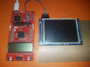
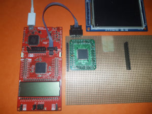
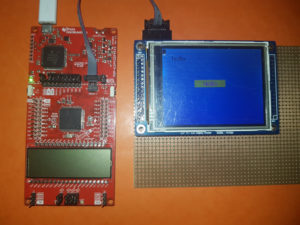
I recently started implementing the HY32D display in MSP432 ARM. I’m using full 16Bit parallel interface via Port B to communicate with the display controller.

Hardware:

  • Display HY32D
    • Controller: SSD1289
    • Interface: 16Bit parallel + 5 control pins
    • Touch Controller: XPT2046
    • Interface: 4-Wire SPI + 1 IRQ
    • Backlight PWM
  • µC MSP432p4111

https://github.com/mr-sven/msp432p4111-hy32d-ssd1289-xpt2046

Some of the display functions are implemented using assembler for best performance results.

Increase MSP432™ SPI Performance – Part 2

Ok, here it is, the Fill function written in assembler.
Due some caching of hardware register addresses in the Core registers, I was able to reduce the following code from 8+ steps to 4.

UCB2TXBUF = data;
while (UCB2STATW & UCBUSY);

The following assembler source is the first full standalone assembler code I wrote. Don’t be mad at me!

ILICTL_POUT   .word 0x40004C42 ; P5OUT
ILIUCI_TXBUF  .word 0x4000280E ; UCB2TXBUF
ILIUCI_STATW  .word 0x40002808 ; UCB2STATW
ILI9341_RAMWR .set 0x2c
ILICTL_DCX    .set 0x0004
UCBUSY        .set 0x0001
 
;############################################################################################
; extern void ILI9341_FillASM(uint16_t color, uint32_t count32);
    .global ILI9341_FillASM
ILI9341_FillASM: .asmfunc
 
Color   .set r0 ; r0 = Color ; Param 0
Count   .set r1 ; r1 = Count ; Param 1
TXBUF   .set r2 ; r2 = ILIUCI_TXBUF
STATW   .set r3 ; r3 = ILIUCI_STATW
POUT    .set r4 ; r4 = ILICTL_POUT
ColorH  .set r5 ; r5 = Color >> 8
Slow    .set r6 ; r6 = Count & 0x0007
Buffer  .set r7
 
    push {r4-r7}
 
; cache hardware register addresses
    ldr TXBUF, ILIUCI_TXBUF
    ldr STATW, ILIUCI_STATW
    ldr POUT, ILICTL_POUT
 
; ILI_COMMAND
    ldrb Buffer, [POUT]
    bic Buffer, Buffer, #ILICTL_DCX
    strb Buffer, [POUT]
 
; transmit ramwr byte
    mov Buffer, #ILI9341_RAMWR
    strb Buffer, [TXBUF]
 
RAMWR_Busy_L: ; wait until transmit
        ldrb Buffer, [STATW]
        tst Buffer, #UCBUSY
        bne RAMWR_Busy_L
 
; ILI_DATA
    ldrb Buffer, [POUT]
    orr Buffer, Buffer, #ILICTL_DCX
    strb Buffer, [POUT]
 
    lsr ColorH, Color, #8 ; Color >> 8
    ands Slow, Count, #0x0007 ; Test if lower bits of count is set
    beq Fast
 
Slow_L: ; Slow data loop
        strb ColorH, [TXBUF] ; Color H
Slow_Busy_L0: ; wait until transmit
            ldrb Buffer, [STATW]
            tst Buffer, #UCBUSY
            bne Slow_Busy_L0
        strb Color, [TXBUF] ; Color L
Slow_Busy_L1: ; wait until transmit
            ldrb Buffer, [STATW]
            tst Buffer, #UCBUSY
            bne Slow_Busy_L1
        subs Slow, Slow, #1
        bne Slow_L ; continue while slow data
 
Fast: ; Fast data
    lsrs Count, Count, #3 ; count >> 3
    beq End ; if count = 0, goto end
 
Fast_L: ; fast data loop
        ; ----------------- Data 0 -----------------
        strb ColorH, [TXBUF] ; Color H
Fast_Busy_L0: ; wait until transmit
            ldrb Buffer, [STATW]
            tst Buffer, #UCBUSY
            bne Fast_Busy_L0
        strb Color, [TXBUF] ; Color L
Fast_Busy_L1: ; wait until transmit
            ldrb Buffer, [STATW]
            tst Buffer, #UCBUSY
            bne Fast_Busy_L1
 
        ; ----------------- Data 1 -----------------
        strb ColorH, [TXBUF] ; Color H
Fast_Busy_L2: ; wait until transmit
            ldrb Buffer, [STATW]
            tst Buffer, #UCBUSY
            bne Fast_Busy_L2
        strb Color, [TXBUF] ; Color L
Fast_Busy_L3: ; wait until transmit
            ldrb Buffer, [STATW]
            tst Buffer, #UCBUSY
            bne Fast_Busy_L3
 
        ; ----------------- Data 2 -----------------
        strb ColorH, [TXBUF] ; Color H
Fast_Busy_L4: ; wait until transmit
            ldrb Buffer, [STATW]
            tst Buffer, #UCBUSY
            bne Fast_Busy_L4
        strb Color, [TXBUF] ; Color L
Fast_Busy_L5: ; wait until transmit
            ldrb Buffer, [STATW]
            tst Buffer, #UCBUSY
            bne Fast_Busy_L5
 
        ; ----------------- Data 3 -----------------
        strb ColorH, [TXBUF] ; Color H
Fast_Busy_L6: ; wait until transmit
            ldrb Buffer, [STATW]
            tst Buffer, #UCBUSY
            bne Fast_Busy_L6
        strb Color, [TXBUF] ; Color L
Fast_Busy_L7: ; wait until transmit
            ldrb Buffer, [STATW]
            tst Buffer, #UCBUSY
            bne Fast_Busy_L7
 
        ; ----------------- Data 4 -----------------
        strb ColorH, [TXBUF] ; Color H
Fast_Busy_L8: ; wait until transmit
            ldrb Buffer, [STATW]
            tst Buffer, #UCBUSY
            bne Fast_Busy_L8
        strb Color, [TXBUF] ; Color L
Fast_Busy_L9: ; wait until transmit
            ldrb Buffer, [STATW]
            tst Buffer, #UCBUSY
            bne Fast_Busy_L9
 
        ; ----------------- Data 5 -----------------
        strb ColorH, [TXBUF] ; Color H
Fast_Busy_L10: ; wait until transmit
            ldrb Buffer, [STATW]
            tst Buffer, #UCBUSY
            bne Fast_Busy_L10
        strb Color, [TXBUF] ; Color L
Fast_Busy_L11: ; wait until transmit
            ldrb Buffer, [STATW]
            tst Buffer, #UCBUSY
            bne Fast_Busy_L11
 
        ; ----------------- Data 6 -----------------
        strb ColorH, [TXBUF] ; Color H
Fast_Busy_L12: ; wait until transmit
            ldrb Buffer, [STATW]
            tst Buffer, #UCBUSY
            bne Fast_Busy_L12
        strb Color, [TXBUF] ; Color L
Fast_Busy_L13: ; wait until transmit
            ldrb Buffer, [STATW]
            tst Buffer, #UCBUSY
            bne Fast_Busy_L13
 
        ; ----------------- Data 7 -----------------
        strb ColorH, [TXBUF] ; Color H
Fast_Busy_L14: ; wait until transmit
            ldrb Buffer, [STATW]
            tst Buffer, #UCBUSY
            bne Fast_Busy_L14
        strb Color, [TXBUF] ; Color L
Fast_Busy_L15: ; wait until transmit
            ldrb Buffer, [STATW]
            tst Buffer, #UCBUSY
            bne Fast_Busy_L15
 
        subs Count, Count, #1
        bne Fast_L ; continue while fast data
 
End:
    pop {r4-r7}
    bx lr
    .endasmfunc

Increase MSP432™ SPI Performance – Part 1

Currently I work on a 240×320 Pixel QVGA Display, connected via SPI. As I wrote this article I mentioned this was a bad idea.

Following calculation:

  • 240 x 320 Pixel = 76.800 Pixel
  • 16 Bit (Color Mode) * 76.800 Pixel = 1.228.800 Bit
  • MSP432P401R SPI max frequency = 24MHz
  • 24.000.000 / 1.228.800 = 19,53125

This makes a maximum Full Screen FPS of round about 20. So for the human eye it is to slow.

Ok, for now I can’t break this limit, but I can try to reach it.

Try One: use eUSCI ISR handler

void UCIA0IsrHandler(void)
{
    switch(UCIA0IV)
    {
    case 0x0004: // UCTXIFG
        if (fill_count & 0x001)
        {
            UCIA0TXBUF = fill_data_h;
        }
        else
        {
            UCIA0TXBUF = fill_data_l;
        }
        fill_count--;
 
        if (fill_count)
        {
            return;
        }
 
        UCIA0IE &= ~(UCTXIE);
        break;
    }
}

Whats the result of this: a bad one. I tried to count the CPU steps until the new byte is pushed to the transmit buffer.

The Disassembler shows 14 steps, I think with ISR Join and Leave I’m over 16, which results in a gap between each byte and the transmission is slower than 20 fps.

There are possibilities to optimize this code, but for me are 16 steps between ISRs too few.

Try Two: Synchronized transmission

#define SendSync(data) \
    UCIA0TXBUF = data; \
    while (UCIA0STAT & UCBUSY);
 
void Fill(uint16_t color, uint32_t count32)
{
    uint8_t a = color >> 8;
    uint8_t b = color;
 
    uint8_t slow = count32 & 0x07;
    if (slow)
    {
        do {
            SendSync(a);
            SendSync(b);
        } while (--slow);
    }
 
    // x8 unrolled
    int count = count32 >> 3;
    if (count)
    {
        do {
            SendSync(a);
            SendSync(b);
 
            SendSync(a);
            SendSync(b);
 
            SendSync(a);
            SendSync(b);
 
            SendSync(a);
            SendSync(b);
 
            SendSync(a);
            SendSync(b);
 
            SendSync(a);
            SendSync(b);
 
            SendSync(a);
            SendSync(b);
 
            SendSync(a);
            SendSync(b);
        } while (--count);
    }
}

This results in 8 Steps for each byte and with a bit logic you reach the 20 fps.
What comes next?, decrease the code size. This can be done using Assembler.
The next part, I hope will contain the Fill function in asm.

First summary

At first I would say: what the heck, (TI) you build a 32Bit ARM Core based on MSP430 but there is only a 8Bit SPI Interface. Why don’t use in addition a transfer mask, that makes it variable in how meany bits to transfer. In my case I could set a 16bit mask until the data can be divided by two and then I can ship 32bit data.

This could make the use of ISR more efficient, because this creates a gap of 64 CPU Steps, which are enough to do other stuff.

MSP432™ Interrupt system

The MSP432™ uses a additional level for interrupts: the Nested Vectored Interrupt Controller (NVIC). Every interrupt you request must be enabled in the NVIC.

To enable for example the Timer_A0_N interrupt you have to call also the NVIC function:

NVIC_EnableIRQ(TA0_N_IRQn);

You can see a list of all interrupts in the msp432p401r.h file, there is a enum type IRQn_Type.

At next you can choose between Code based and RAM based interrupt vectors.

Code based interrupt

The Code based interrupts are hardlinked between the IVT and the ISR.

To put a ISR in the IVT you have define the ISR in your application first:

// ISR for Timer_A0_N
void Timer_A0_N (void)
{
	// handle IRQ
}

At default the IVT is defined in the msp432_startup_ccs.c file, there you have to declare your function:

/* External declarations for the interrupt handlers used by the application. */
/* To be added by user */
extern void Timer_A0_N (void);

At last you assign the function to the IVT:

#pragma DATA_SECTION(interruptVectors, ".intvecs")
void (* const interruptVectors[])(void) =
{
	(void (*)(void))((uint32_t)&__STACK_END),
	...
	Timer_A0_N,                             /* TA0_N ISR                 */
	...
};

In the document SLAA656 (MSP432™ Platform Porting Guide) version 2015-03 is witten the old „#pragma vector“ method should also work, but at my tests the compiler thows some errors on it.

RAM based interrupt

RAM based interrupts can be used in oder if you have multiple applications running on your MSP and every application has it’s own ISRs.

For the use of RAM based interrupts I recommend to use the MSP432 DriverLib Interrupt API. You have to create a RAM table and manage the IV entrys and the API is straight forward and implements all the needed functions.

You can start using Code based interrupts, if you call the Interrupt_registerInterrupt function at first time, it will copy the whole IVT from Code to RAM.

The Interrupt_registerInterrupt and Interrupt_unregisterInterrupt does not enable or disable the interrupt, you have to call Interrupt_enableInterrupt and Interrupt_disableInterrupt manually.

As example the timer interrupt:

// from MSP432 DriverLib
#include "interrupt.h"
 
// ISR for Timer_A0_N
void Timer_A0_N (void)
{
	// handle IRQ
}
 
void main(void)
{
	...
	Interrupt_registerInterrupt(INT_TA0_N, Timer_A0_N);
	Interrupt_enableInterrupt(INT_TA0_N);
	...
}

MSP432™ Clock System speed

Changing the Clock Speed of the MSP432™ is a bit tricky. First you have to unlock the registers, then you can change the DCO speed. You can ajust the clock using the following DCO values.

DCORSEL min MHz normal (DCOTUNE = 0) MHz max MHz
DCORSEL_0 1 1.5 2
DCORSEL_1 2 3 4
DCORSEL_2 4 6 8
DCORSEL_3 8 12 16
DCORSEL_4 16 24 32
DCORSEL_5 32 48 64


Read more in document SLAU356A (MSP432P4xx Family Technical Reference Manual) version 2015-04 section 5.3.

You can increase or decrease the speed using the DCOTUNE Register to any value between min and max. For the correct values of DCOTUNE consult the document SLAA658 (Multi-Frequency Range and Tunable DCO on MSP432P4xx) version 2015-03. These values can be obtained from the TLV.

TLV->rDCOIR_MAXNEGTUNE_RSEL04; // DCO IR mode: Max Negative Tune for DCORSEL 0 to 4
TLV->rDCOIR_MAXPOSTUNE_RSEL04; // DCO IR mode: Max Positive Tune for DCORSEL 0 to 4
TLV->rDCOIR_MAXNEGTUNE_RSEL5; // DCO IR mode: Max Negative Tune for DCORSEL 5
TLV->rDCOIR_MAXPOSTUNE_RSEL5; // DCO IR mode: Max Positive Tune for DCORSEL 5

The CSKEY register is described as CSACC in the documentation, but in Code Composer Studio the register has still the name CSKEY.

Example change DCO to IR and 48MHz:

CSKEY = 0x695A; // unlock CS registers
CSCTL0 = 0; // reset DCO settings
CSCTL0 = DCORSEL_5; // select DCO 5 (48MHz)
CSCTL1 = SELA__REFOCLK | SELS__DCOCLK | SELM__DCOCLK; // ACLK = REFOCLK, SMCLK = MCLK = DCOCLK
CSKEY = 0; // lock CS registers

MSP430 InfoA (Calibrationdata) lost

Nachdem ich angefangen habe einen MSP430F2616 über BSL zu programmieren, habe ich zwischendurch ausversehen das Kalibrierungsregister Info A gelöscht. Zum Glück hatte ich einen Dump. Aber wie es der Zufall so will, habe ich beim dumpen auch noch die falsche Länge angegeben, was also dazu führte, dass ich die letzten beiden Register nicht hatte. Das waren ausgerechnet auch noch die für den 1MHz Takt.

Nachdem ich versucht habe, die letzten beiden Register durch errechnen, auslesen und vergleichen von anderen MSPs zu rekonstruieren, habe ich mich dann doch auf die Suche im Internet gemacht.

Nach einer Weile bin ich dann auf einen Artikel im TI Forum gestoßen, dieser Verwies dann auf das Paket „slac163“ (MSP430F21x2 Code Examples) und die darin enthaltene Datei „msp430x21x2_dco_flashcal.c“.

Das Programm ist recht simpel aufgebaut und erlaubt es zumindest die CPU Takt Kalibrierungsregister neu zu errechnen, alles was man dazu benötigt ist ein 32kHz Uhrenquarz, welcher an XIN und XOUT angeschlossen wird.

Da man solch ein Uhrenquarz so ziemlich in jedem Gerät findet, war das kein Problem.

Nach dem man das Programm geladen und gestartet hat, würde das Programm eine an P1.0 angeschlossene LED einschalten, sobald die Kalibrierungsdaten für 1MHz, 8MHz, 12MHz und 16 MHz wieder in das Kalibrierungsregister geschrieben wurden.

Da ich aber keine LED an diesem Port hatte, habe ich einfach ein paar Sekunden gewartet. Danach konnte ich das Info A Register auslesen und dort waren alle Takt Daten wieder vorhanden.

Jetzt konnte ich die Sicherung wieder vervollständigen und das Register komplett wiederherstellen.

Eine Interessante Möglichkeit bietet dies zudem, man kann noch anderen Takt Frequenzen kalibrieren lassen. Optimal sind welche, die sich durch 4096Hz teilen lassen.

Ich habe in einem Beitrag gelesen, dass es je nach Chip möglich ist diesen bis auf 19-20MHz zu Takten. Der wird dann aber bestimmt sehr instabil.


Zur Sicherheit habe ich nun das komplette Info A Register mit in das Programm integriert, sodass dieses auch beim BSL Flash wieder gesetzt wird.


Jetzt noch zur Frage, warum BSL?, weil ich kein MSP-FET für den JTAG habe und der Chip kein Spy-Bi-Wire hat, welches ich über ein Launchpad benutzen könnte.