Increase MSP432™ SPI Performance – Part 2

Ok, here it is, the Fill function written in assembler.
Due some caching of hardware register addresses in the Core registers, I was able to reduce the following code from 8+ steps to 4.

UCB2TXBUF = data;
while (UCB2STATW & UCBUSY);

The following assembler source is the first full standalone assembler code I wrote. Don’t be mad at me!

ILICTL_POUT   .word 0x40004C42 ; P5OUT
ILIUCI_TXBUF  .word 0x4000280E ; UCB2TXBUF
ILIUCI_STATW  .word 0x40002808 ; UCB2STATW
ILI9341_RAMWR .set 0x2c
ILICTL_DCX    .set 0x0004
UCBUSY        .set 0x0001
 
;############################################################################################
; extern void ILI9341_FillASM(uint16_t color, uint32_t count32);
    .global ILI9341_FillASM
ILI9341_FillASM: .asmfunc
 
Color   .set r0 ; r0 = Color ; Param 0
Count   .set r1 ; r1 = Count ; Param 1
TXBUF   .set r2 ; r2 = ILIUCI_TXBUF
STATW   .set r3 ; r3 = ILIUCI_STATW
POUT    .set r4 ; r4 = ILICTL_POUT
ColorH  .set r5 ; r5 = Color >> 8
Slow    .set r6 ; r6 = Count & 0x0007
Buffer  .set r7
 
    push {r4-r7}
 
; cache hardware register addresses
    ldr TXBUF, ILIUCI_TXBUF
    ldr STATW, ILIUCI_STATW
    ldr POUT, ILICTL_POUT
 
; ILI_COMMAND
    ldrb Buffer, [POUT]
    bic Buffer, Buffer, #ILICTL_DCX
    strb Buffer, [POUT]
 
; transmit ramwr byte
    mov Buffer, #ILI9341_RAMWR
    strb Buffer, [TXBUF]
 
RAMWR_Busy_L: ; wait until transmit
        ldrb Buffer, [STATW]
        tst Buffer, #UCBUSY
        bne RAMWR_Busy_L
 
; ILI_DATA
    ldrb Buffer, [POUT]
    orr Buffer, Buffer, #ILICTL_DCX
    strb Buffer, [POUT]
 
    lsr ColorH, Color, #8 ; Color >> 8
    ands Slow, Count, #0x0007 ; Test if lower bits of count is set
    beq Fast
 
Slow_L: ; Slow data loop
        strb ColorH, [TXBUF] ; Color H
Slow_Busy_L0: ; wait until transmit
            ldrb Buffer, [STATW]
            tst Buffer, #UCBUSY
            bne Slow_Busy_L0
        strb Color, [TXBUF] ; Color L
Slow_Busy_L1: ; wait until transmit
            ldrb Buffer, [STATW]
            tst Buffer, #UCBUSY
            bne Slow_Busy_L1
        subs Slow, Slow, #1
        bne Slow_L ; continue while slow data
 
Fast: ; Fast data
    lsrs Count, Count, #3 ; count >> 3
    beq End ; if count = 0, goto end
 
Fast_L: ; fast data loop
        ; ----------------- Data 0 -----------------
        strb ColorH, [TXBUF] ; Color H
Fast_Busy_L0: ; wait until transmit
            ldrb Buffer, [STATW]
            tst Buffer, #UCBUSY
            bne Fast_Busy_L0
        strb Color, [TXBUF] ; Color L
Fast_Busy_L1: ; wait until transmit
            ldrb Buffer, [STATW]
            tst Buffer, #UCBUSY
            bne Fast_Busy_L1
 
        ; ----------------- Data 1 -----------------
        strb ColorH, [TXBUF] ; Color H
Fast_Busy_L2: ; wait until transmit
            ldrb Buffer, [STATW]
            tst Buffer, #UCBUSY
            bne Fast_Busy_L2
        strb Color, [TXBUF] ; Color L
Fast_Busy_L3: ; wait until transmit
            ldrb Buffer, [STATW]
            tst Buffer, #UCBUSY
            bne Fast_Busy_L3
 
        ; ----------------- Data 2 -----------------
        strb ColorH, [TXBUF] ; Color H
Fast_Busy_L4: ; wait until transmit
            ldrb Buffer, [STATW]
            tst Buffer, #UCBUSY
            bne Fast_Busy_L4
        strb Color, [TXBUF] ; Color L
Fast_Busy_L5: ; wait until transmit
            ldrb Buffer, [STATW]
            tst Buffer, #UCBUSY
            bne Fast_Busy_L5
 
        ; ----------------- Data 3 -----------------
        strb ColorH, [TXBUF] ; Color H
Fast_Busy_L6: ; wait until transmit
            ldrb Buffer, [STATW]
            tst Buffer, #UCBUSY
            bne Fast_Busy_L6
        strb Color, [TXBUF] ; Color L
Fast_Busy_L7: ; wait until transmit
            ldrb Buffer, [STATW]
            tst Buffer, #UCBUSY
            bne Fast_Busy_L7
 
        ; ----------------- Data 4 -----------------
        strb ColorH, [TXBUF] ; Color H
Fast_Busy_L8: ; wait until transmit
            ldrb Buffer, [STATW]
            tst Buffer, #UCBUSY
            bne Fast_Busy_L8
        strb Color, [TXBUF] ; Color L
Fast_Busy_L9: ; wait until transmit
            ldrb Buffer, [STATW]
            tst Buffer, #UCBUSY
            bne Fast_Busy_L9
 
        ; ----------------- Data 5 -----------------
        strb ColorH, [TXBUF] ; Color H
Fast_Busy_L10: ; wait until transmit
            ldrb Buffer, [STATW]
            tst Buffer, #UCBUSY
            bne Fast_Busy_L10
        strb Color, [TXBUF] ; Color L
Fast_Busy_L11: ; wait until transmit
            ldrb Buffer, [STATW]
            tst Buffer, #UCBUSY
            bne Fast_Busy_L11
 
        ; ----------------- Data 6 -----------------
        strb ColorH, [TXBUF] ; Color H
Fast_Busy_L12: ; wait until transmit
            ldrb Buffer, [STATW]
            tst Buffer, #UCBUSY
            bne Fast_Busy_L12
        strb Color, [TXBUF] ; Color L
Fast_Busy_L13: ; wait until transmit
            ldrb Buffer, [STATW]
            tst Buffer, #UCBUSY
            bne Fast_Busy_L13
 
        ; ----------------- Data 7 -----------------
        strb ColorH, [TXBUF] ; Color H
Fast_Busy_L14: ; wait until transmit
            ldrb Buffer, [STATW]
            tst Buffer, #UCBUSY
            bne Fast_Busy_L14
        strb Color, [TXBUF] ; Color L
Fast_Busy_L15: ; wait until transmit
            ldrb Buffer, [STATW]
            tst Buffer, #UCBUSY
            bne Fast_Busy_L15
 
        subs Count, Count, #1
        bne Fast_L ; continue while fast data
 
End:
    pop {r4-r7}
    bx lr
    .endasmfunc

Increase MSP432™ SPI Performance – Part 1

Currently I work on a 240×320 Pixel QVGA Display, connected via SPI. As I wrote this article I mentioned this was a bad idea.

Following calculation:

  • 240 x 320 Pixel = 76.800 Pixel
  • 16 Bit (Color Mode) * 76.800 Pixel = 1.228.800 Bit
  • MSP432P401R SPI max frequency = 24MHz
  • 24.000.000 / 1.228.800 = 19,53125

This makes a maximum Full Screen FPS of round about 20. So for the human eye it is to slow.

Ok, for now I can’t break this limit, but I can try to reach it.

Try One: use eUSCI ISR handler

void UCIA0IsrHandler(void)
{
    switch(UCIA0IV)
    {
    case 0x0004: // UCTXIFG
        if (fill_count & 0x001)
        {
            UCIA0TXBUF = fill_data_h;
        }
        else
        {
            UCIA0TXBUF = fill_data_l;
        }
        fill_count--;
 
        if (fill_count)
        {
            return;
        }
 
        UCIA0IE &= ~(UCTXIE);
        break;
    }
}

Whats the result of this: a bad one. I tried to count the CPU steps until the new byte is pushed to the transmit buffer.

The Disassembler shows 14 steps, I think with ISR Join and Leave I’m over 16, which results in a gap between each byte and the transmission is slower than 20 fps.

There are possibilities to optimize this code, but for me are 16 steps between ISRs too few.

Try Two: Synchronized transmission

#define SendSync(data) \
    UCIA0TXBUF = data; \
    while (UCIA0STAT & UCBUSY);
 
void Fill(uint16_t color, uint32_t count32)
{
    uint8_t a = color >> 8;
    uint8_t b = color;
 
    uint8_t slow = count32 & 0x07;
    if (slow)
    {
        do {
            SendSync(a);
            SendSync(b);
        } while (--slow);
    }
 
    // x8 unrolled
    int count = count32 >> 3;
    if (count)
    {
        do {
            SendSync(a);
            SendSync(b);
 
            SendSync(a);
            SendSync(b);
 
            SendSync(a);
            SendSync(b);
 
            SendSync(a);
            SendSync(b);
 
            SendSync(a);
            SendSync(b);
 
            SendSync(a);
            SendSync(b);
 
            SendSync(a);
            SendSync(b);
 
            SendSync(a);
            SendSync(b);
        } while (--count);
    }
}

This results in 8 Steps for each byte and with a bit logic you reach the 20 fps.
What comes next?, decrease the code size. This can be done using Assembler.
The next part, I hope will contain the Fill function in asm.

First summary

At first I would say: what the heck, (TI) you build a 32Bit ARM Core based on MSP430 but there is only a 8Bit SPI Interface. Why don’t use in addition a transfer mask, that makes it variable in how meany bits to transfer. In my case I could set a 16bit mask until the data can be divided by two and then I can ship 32bit data.

This could make the use of ISR more efficient, because this creates a gap of 64 CPU Steps, which are enough to do other stuff.

Analyse des Tolino Shine

Nachdem der Tolino Shine bei uns zu Hause eingetrudelt ist, habe ich mich damit ein wenig beschäftigt.

Im Internet habe ich auch gleich ein paar Informationen gefunden, bezüglich root etc., leider ist das rooten ohne das Gerät zu öffnen seit dem Update 1.2 nicht mehr möglich, zumindest bis jetzt.

Wenn man doch dazu kommt und das Gerät öffnet, findet man dort, netter weise eine Micro SD die in einem Sockel Steckt, was natürlich das Verwandeln zu einem Ziegelstein nahezu unmöglich macht.

Nachdem ich ein paar Bilder eines geöffneten Shine angeschaut hatte und die Position der Seriellen Console gesehen habe, dachte ich mir, da müsste man doch ran kommen ohne das Gerät ganz aus einander zu bauen.

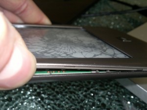
Mit einem starken Daumennagel konnte ich den Tolino, ohne das Gehäuse zu beschädigen, an der Seite öffnen. Bingo da lässt sich mit einer kleinen Kabelbrücke ran kommen.

Serielle Console

Serielle Console

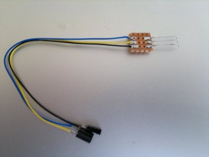
Nun denn habe ich meinen 3,3V Seriell Wandler ausgepackt und ein Stück Flachbandkabel mit dem Rastermaß von 2,54mm, die Litze besteht aus jeweils einem Draht, sodass das ganze schön formstabil bleibt.

Die Enden habe ich ca. 2mm ab-isoliert und 45° nach unten gebogen. Länger als 2mm dürfen die Enden nicht sein, da es sonst nicht zwischen Platine und Display passt.

Adapterkabel

Adapterkabel

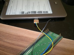
Ein bisschen fummelig stellte sich dann das richtige Platzieren der Kabelbrücke heraus, danach tat dann das Gehäuse sein Übriges um das Kabel in Position zu halten.

Alles in allem war ich in 5 Minuten damit fertig und hatte die Root Console des Tolino vor mir.

Anschluss

Anschluss

Der Rest war Fleißarbeit, einfach start adbd eingeben und schon startete der ADB. Dann noch schnell die su Binary installieren.

Schon konnte man das ganze wieder entfernen und das Gehäuse zu machen. Keine Schramme, kein Garnichts, sieht aus wie neu.

So konnte ich dann auf dem Tolino mit der Version 1.3.0 alle schönen Apps (Launcher, Button, …) wieder installieren und das alles ohne das Gerät auseinander bauen zu müssen.

Man sollte sich dann noch in einem der Startskripte eine ADB Backdoor einbauen, damit dieser auch nach einem Neustart wieder da ist.

Ach ja, bevor ich irgendetwas gemacht habe, habe ich mir erst mal die eingebaute SD Karte per dd auf eine Externe gesichert (Sicher ist sicher!).

SmartCard programming in C#

SmartCard programming in C#Because I’ve not found any complete wrapper lib for for the winscard.dll in C# I created it. If there is something missing, feel free to contact me.

SmartCard programming in C#

Kamailio Dialplan Module

Habe ein kleines Programm geschrieben mit dem man die DB_TEXT Tabelle für das Dialplan Modul des Kamailio editieren und erstellen kann. Ist halt etwas übersichticher als wenn man das mit dem Editor mach.

Das Programm ist unter Programming -> C# zu finden.